Description
The vendor for the TMA is Tekniker. They will be providing a PDF documents for operating the TMA. In an effort to have consistency across software documentation I will be transcibing the TMA documents onto this TMA Technote.
Acronyms
| Acronym | Definition | Notes |
|---|---|---|
| AZ_AXIS | Azimuth Axes | |
| AZ_CW | Azimuth Cable Wrap | |
| CAM_CW | Camera Cable Wrap | |
| DP | Deployable Platform | |
| EIB | Encoder system | Heidenhain calls the actual device EIB 8000 |
| EL_AXIS | Main Elevation Axes | |
| HMI | Human Machine Interface | |
| LP | Locking Pins | |
| MC | mirror cover | |
| MPS | main power supply | |
| OSS | Oil Supply System | |
| TF | Transfer Function |
CCW Aux Cabinet
Below you will find useful instructions when working on CCW Auxiliary Cabinet.
Turning on the CCW Aux Cabinet
- Turn on the Rotator Cabinet, this will provide power to the CCW Aux Cabinet
- Turn on the CCW Aux Cabinet by the circular knob on the left of the cabinet.
- Wait 2 minutes for the CCW Aux Cabinet to fully power on.
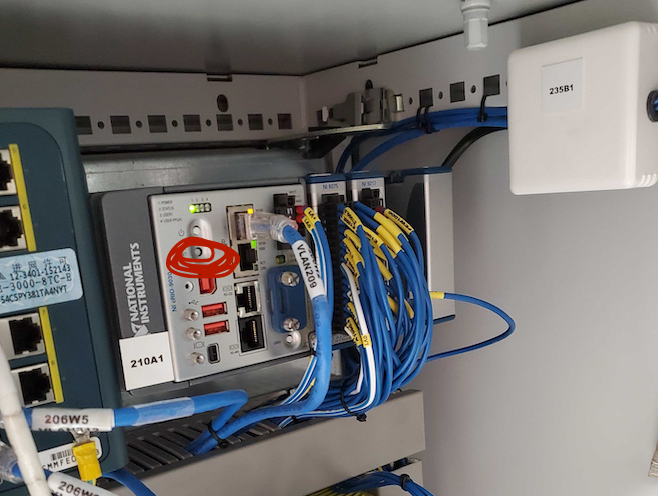
- Restart the cRIO by pressing the reset button shown below.
Done! The cabinet should now be powered on.
CCW Operation
Below you will find useful instructions for operating the CCW.
Operating EUI
- Execute Turning on the CCW Aux Cabinet
- Open a terminal window.
- Execute
ulimit -s 100000.- Navigate to Labview 2018
cd /usr/local/natinst/LabVIEW-2018-64.- Start Labview 2018
./labview.- Open the EUI Main project.
- Find any missing libraries in the 2018 path.
- Close any warning
Warning
If SAL kernel crashes computer must be restarted
Master Server List
The table below is a list of Server / Computers that are used to control the Telescope Mount Assemble (TMA). The table can be used to learn about the physical location of the Server / Computer along with details on how to access the Server / Computer.
| Server / Computer | Location | Details |
|---|---|---|
| CCW Cabinet | 3rd Floor, near clean room | Need to use Labview EUI to acces control software |
Safety Interlocks
Below you will find useful instructions when working on the TMA Safety Interlocks.
Clearing Interlocks when Connected to SAL
- Send clearerror. On a SAL publisher send the command “clearerror”
- Sieze Control. Go to main menu and select “GUI”
- Override the interlocks, go to the Safety menu and select “override interlocks”
- Clear the erros, go to the CCW and select “clear errors”
- Release overrides, go to Safety and select “realease ovverride”
- Relinquish Control, to to main menu and select “SAL”
Clearing Interlocks when NOT Connected to SAL
- Override the interlocks, go to the Safety menu and select “override interlocks”
- Clear the erros, go to the CCW and select “clear errors”
- Release overrides, go to Safety and select “realease ovverride”
Disconnecting the CCW Interlock Systems from Rotator
1. Familiarize yourself with the Safety Interlock Connections. One connection leads to the Rotator, the other connection is a standalone connection that is tied to the CCW Auxiliary Control Cabinet. Below circled in red are the connections.
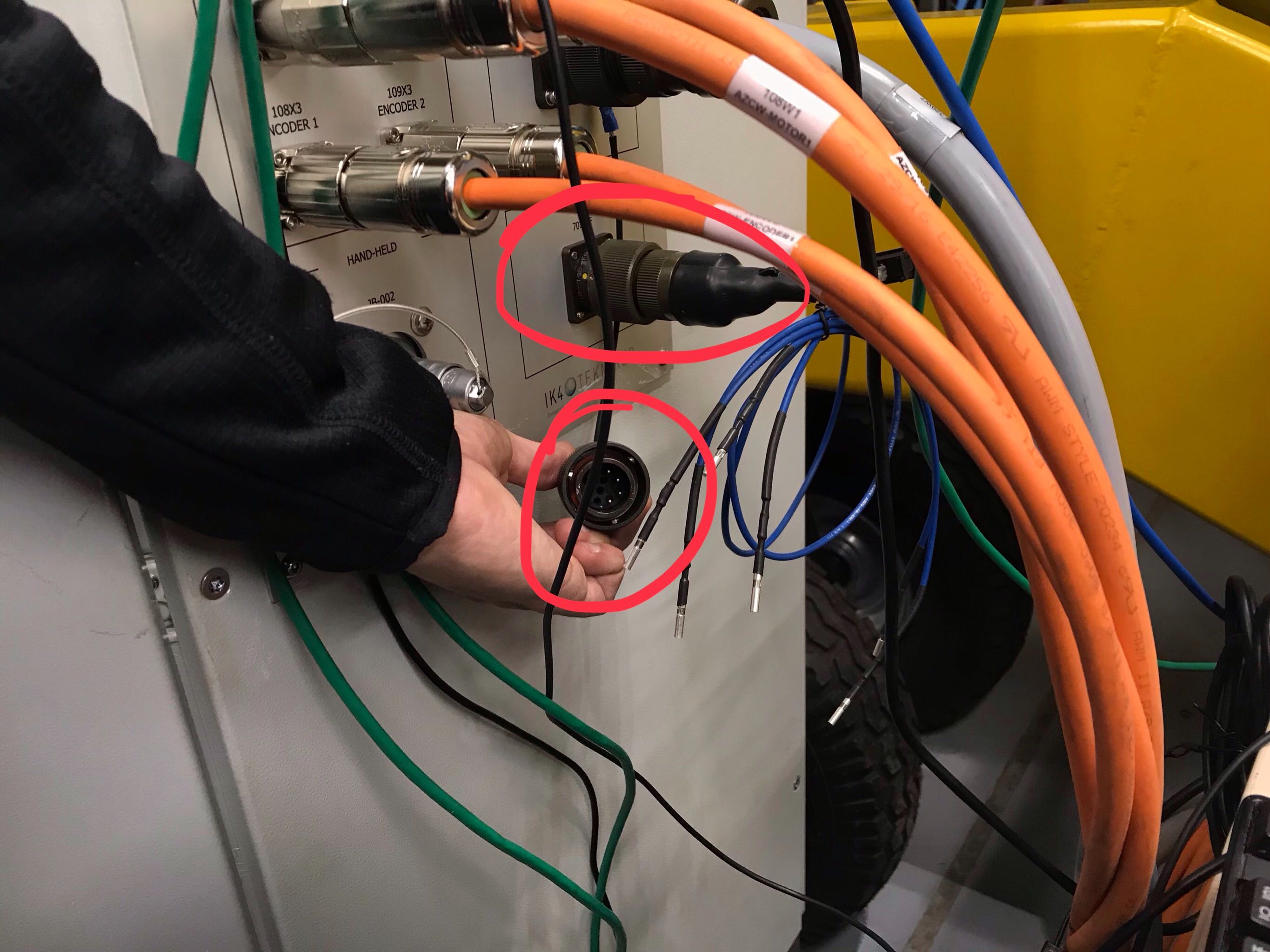
2. Connect the Standalone Safety Interlock connector into the CCW Auxiliary Control Cabinet.
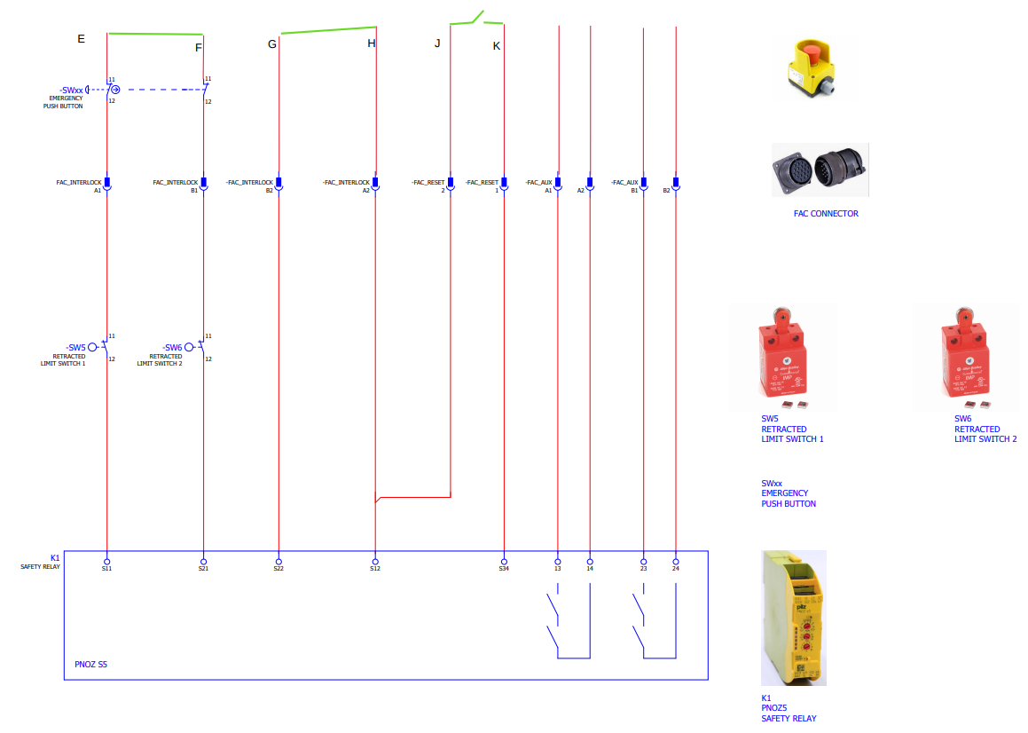
3. Wire the removed Safety Interlock cable that is now only connected to the Rotator cabent as described below
Connecting the CCW Interlock Systems to Rotator
Todo
Write this section
TMA Simulation Configurations
Here you will find sets of instructions that document the different configurations that are avilable. Each of these configurations test a certain functionality. In order of increasing complexity the following are the configurations available to the TMA software.
HMI NSV Simulation
The following instructions will help you understand and configure a simulation environment for the TMA Humane Machine Interface, which can be shortened to HMI. This is the most basic simulation that can be done. This is called the “HMI NSV Simulation” because we are simulation only the NSV’s (Network Shared Variables) on a Windows machine to verify that the HMI is comminicating to the NSV’s. Random NSV’s will be generated so we will see the HMI behave eratically. The meat and potatoes of this configuration is to modify a configuration file to have the right IP addresses which point to the NSV hosting Windows machine.
- Install the HMI, if you have not done so you can find the instructions here [TO DO]
- On a Windows machine
download the NSV Simulator.- Identify the IP Address of the Windows machine. The IP address that I set my windows machine to is 192.168.1.11. Manually set yours if you need to.
- Identify the IP Address of the CentOS machine which is running the HMI. I manually set mine to be 192.168.1.10. Manually set yours if you need to.
- Connect both machines to a switch and verify that the CentOS and Windows machine can ping each other.
Note
At this point we are confident that both machines can communicate with each other, we continue by editing configuration files of the HMI. The specific repo name is “HMIComputers”. This repository contains the LabVIEW GUI which is referred to as the HMI.
- Open HMICOmputers/Configuration/HMIConfig.xml. This file contains paths, IP Addresses, and locations to various elements of the HMI.
- Look for a tag named <ErrorTaskDirectoryPath dim=’[5]’ type=’String’>. There will be a series of <String> tags below. These series of tags make a path to the ErrorHistory folder. Modify these strings to the path of your local machine. Don’t forget to update the integer value ‘5’ if you change the number of <String> tags.
- Look for a tag named <TMA_Management_Linux_Options mems=”3”>. There will be a nested tag named <Working_Path type=”Path”>/home/Andrew/gitrepos/lsst/tma_management/build</Working_Path>. Modify this path to the path of your local machine.
- Look for a tag named <WindowTelemetryDirectoryPath dim=’[5]’ type=’String’>. There will be a series of <String> tags below. These series of tags make a path to the WindowsLogging folder. Modify these strings to the path of your local machine. Don’t forget to update the integer value ‘5’ if you change the number of <String> tags. We are done editing this file, save and close.
- Open HMIComputers/Configuration/HMITelemetryVariablesURLs.ini. This file contains URL’s, IP’s, and other configuration tags.
- Do a global search for 10.1.22.154 and replace these with the IP address of the Windows machine running the NSV Simulator. In my case I will be replacing them with 192.168.1.11. At the time of writing this document there are 1116 occurances when doing a global search and replace.
- Do a global search for 192.168.209.10 and replace these with the IP address of the Windows machine running the NSV Simulator. In my case I will be replacing them with 192.168.1.11. At the time of writing this document there are 282 occurances when doing a global search and replace.
- Well done! The EUI is now configured to operate with the NSV Simulator. Open HMI as you normally would
Todo
Add link for opening the EUI